Unlocking Circuit Secrets Schematic Diagram Symbols and Their Meaning

Imagine trying to assemble a complex piece of furniture without instructions. Frustrating, right? Schematic diagrams serve as the instruction manual for electronic circuits. Understanding these visual representations is fundamental to designing, building, and troubleshooting any electrical system.
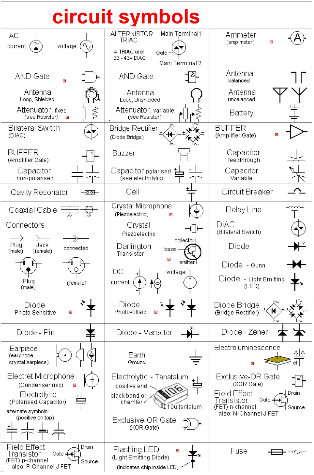
Schematic diagram symbols are the visual vocabulary of electronics. Each symbol represents a specific electronic component, such as a resistor, capacitor, or transistor. These graphical elements, combined with connecting lines, illustrate the flow of electricity and the interconnections between components within a circuit. Without a firm grasp of these symbols, the world of electronics remains a cryptic puzzle.
Mastering this visual language unlocks the secrets of electronic circuits. It empowers you to decipher circuit functionality, troubleshoot malfunctions, and even design your own electronic creations. Whether you’re a seasoned engineer or a budding electronics enthusiast, a solid understanding of schematic diagram symbols is essential.
This guide delves into the intricacies of schematic diagram symbols and their meanings. We'll explore common symbols, their historical context, and their significance in modern electronics. From basic components to more complex integrated circuits, you’ll gain a deeper appreciation for the power of these symbolic representations.
The origin of schematic diagram symbols can be traced back to the early days of electrical engineering. As circuits became more complex, a standardized system of representation became necessary. Over time, a universal set of symbols emerged, allowing engineers across the globe to communicate circuit designs efficiently and accurately. These symbols have evolved, reflecting advancements in technology and the ever-expanding world of electronic components.
One of the primary issues related to schematic diagram symbols is the potential for misinterpretation. Variations in symbol styles and the introduction of new symbols can sometimes lead to confusion. Staying up-to-date with current standards and referencing reliable resources is crucial for accurate interpretation.
For instance, a resistor is represented by a zigzag line. A capacitor is often depicted as two parallel lines. A diode, a component that allows current to flow in only one direction, is symbolized by a triangle pointing towards a line.
Understanding schematic symbols provides several key benefits. First, it facilitates clear communication among engineers and technicians. Second, it simplifies circuit analysis and troubleshooting. Third, it enables efficient design and prototyping of new electronic devices.
To improve your understanding, consider actively practicing reading and interpreting schematics. Start with simple circuits and gradually progress to more complex designs. Utilizing online simulators can also be extremely beneficial, allowing you to visualize circuit behavior and test your understanding of the symbols.
A simple checklist for reading a schematic includes: identifying the power source, tracing the current flow, understanding the function of each component, and verifying the connections between components. This systematic approach ensures a comprehensive understanding of the circuit's operation.
Advantages and Disadvantages of Standardized Schematic Symbols
| Advantages | Disadvantages |
|---|---|
| Universal understanding across different languages and regions | Can be overwhelming for beginners due to the sheer number of symbols |
| Facilitates efficient communication and collaboration among engineers | Variations in standards can sometimes lead to confusion |
| Simplifies troubleshooting and circuit analysis | Requires consistent updating of knowledge to stay current with new symbols and standards. |
Five best practices for using schematic symbols include: adhering to established standards, using clear and concise labels, maintaining consistency throughout the diagram, ensuring adequate spacing between symbols, and regularly reviewing and updating the diagram as needed.
Real-world examples of schematic diagrams include circuit diagrams for smartphones, computers, televisions, and automobiles. These diagrams illustrate the complex interconnections of various electronic components within these devices.
One challenge in using schematic diagrams is keeping up with evolving standards. The solution is to consult regularly updated resources and participate in industry forums.
Frequently Asked Questions:
1. What is a schematic diagram? A schematic diagram is a graphical representation of an electrical circuit.
2. Why are schematic diagrams important? They are essential for designing, building, and troubleshooting circuits.
3. Where can I learn more about schematic diagram symbols? Online resources, textbooks, and industry publications offer extensive information.
4. How do I interpret a complex schematic? Start by identifying the power source and trace the flow of current through the circuit.
5. What are some common schematic diagram symbols? Common symbols include resistors, capacitors, diodes, and transistors.
6. Are there different standards for schematic symbols? Yes, variations exist, highlighting the importance of adhering to a specific standard.
7. What software can I use to create schematic diagrams? Several software tools are available, ranging from free online tools to professional design software.
8. How can I improve my understanding of schematic diagrams? Practice reading and interpreting schematics regularly and use online simulators.
Tips and tricks for understanding schematics include: focus on the flow of current, break down complex diagrams into smaller sections, and use online simulators to visualize circuit behavior.
In conclusion, schematic diagram symbols are the fundamental building blocks of understanding and working with electronic circuits. From the simplest resistor to the most complex integrated circuit, these symbols provide a concise and universal language for communicating complex electronic designs. Mastering this visual vocabulary is essential for anyone involved in electronics, from hobbyists to seasoned engineers. Understanding the historical context, common symbols, and the importance of standardization helps avoid misinterpretations and ensures clear communication within the field. By embracing best practices and continuously learning, you can unlock the full potential of schematic diagrams and confidently navigate the intricate world of electronics. Begin exploring the fascinating realm of circuit design today and empower yourself with the knowledge to bring your electronic ideas to life.
Texas cdl permit secrets ace the test
Unlocking your financial clarity wells fargo statements
Decoding the buzz top mosquito killers according to consumer reports


.jpg)


