Decoding Electrical Schematics: Your Guide to Circuit Symbols

Imagine trying to assemble a complex piece of furniture without instructions. Frustrating, right? Electrical schematics are the instruction manuals of the electrical world. They utilize a standardized visual language of symbols, representing various electrical and electronic components, to communicate the design and function of circuits. Understanding these symbols is essential for anyone working with electricity, from seasoned electricians to hobbyist electronics enthusiasts.
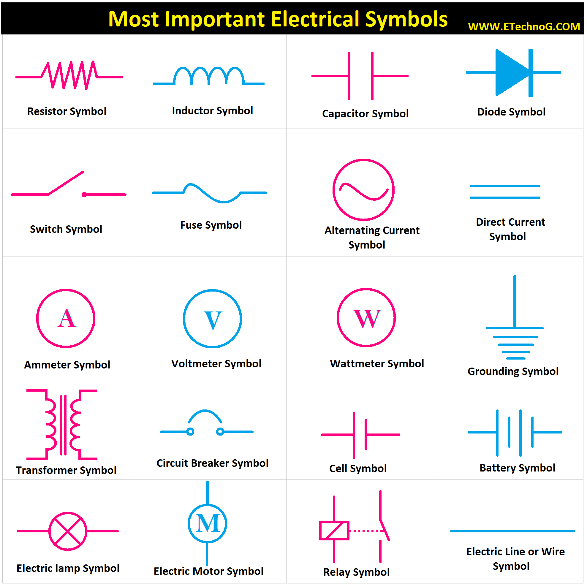
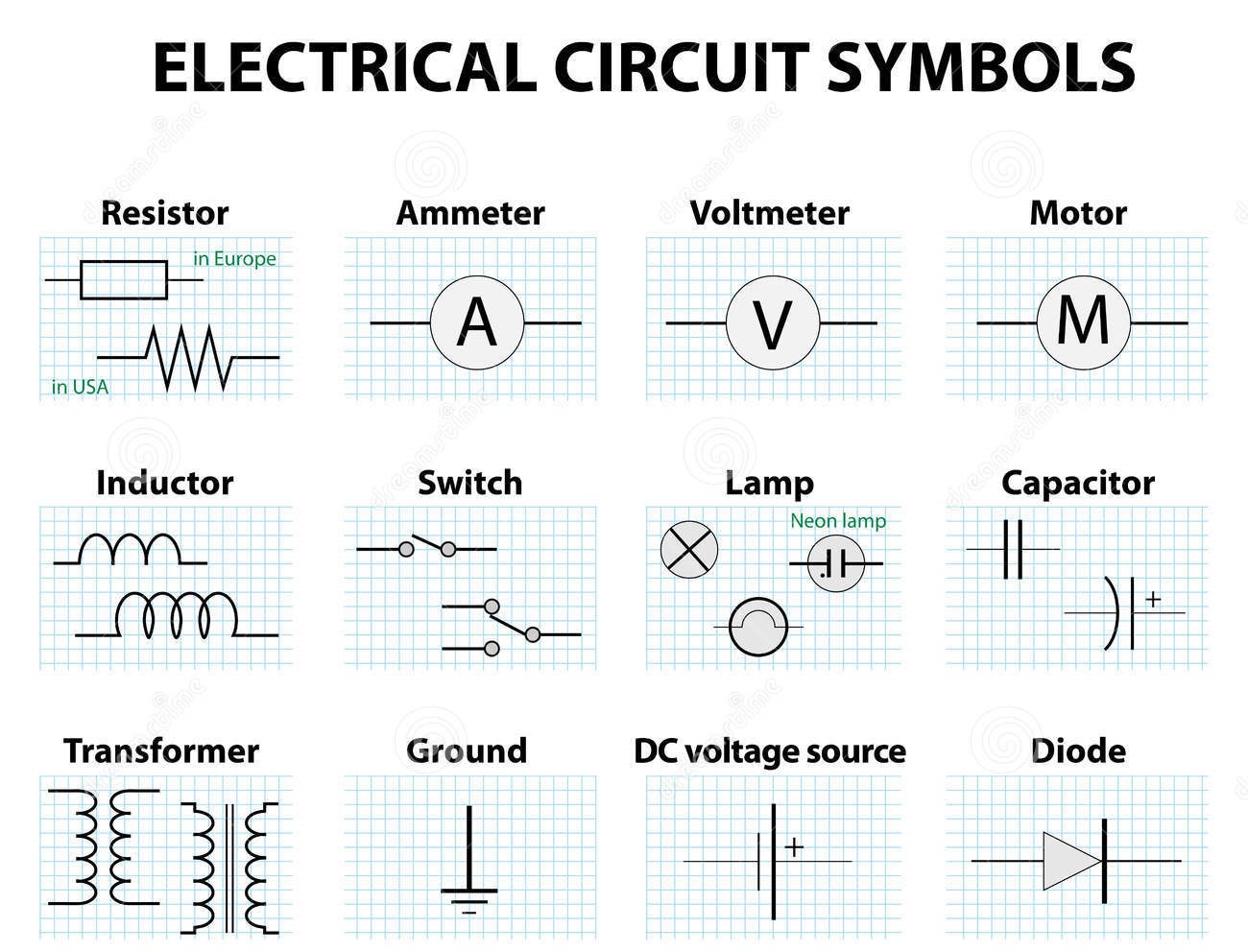
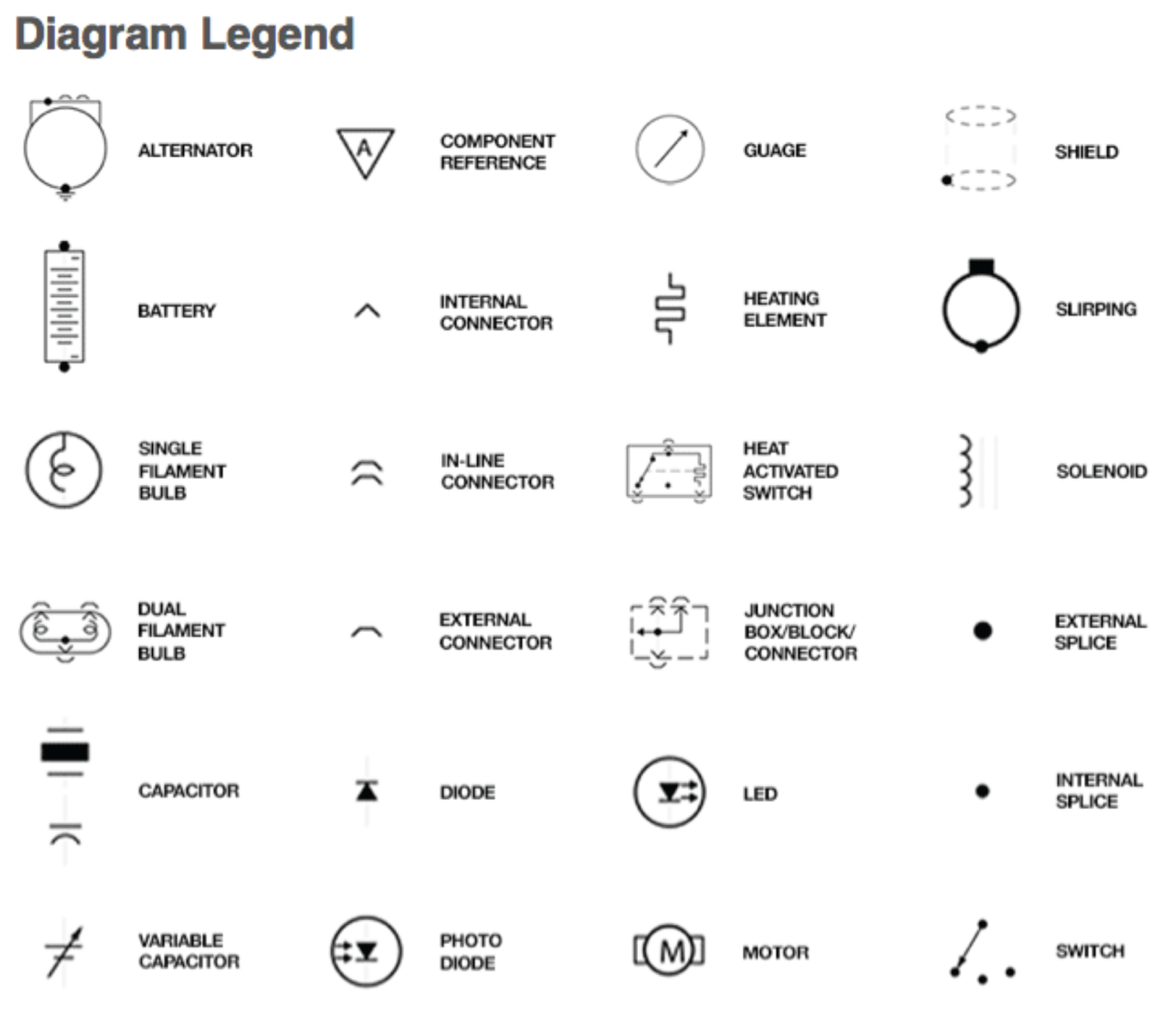
Electrical schematic symbols represent a vast library of components, from simple switches and resistors to complex integrated circuits. These symbols allow engineers and technicians to communicate design intent clearly and concisely. This visual language transcends linguistic barriers, enabling collaboration and understanding across the globe. By mastering these symbols, you unlock the ability to design, analyze, troubleshoot, and repair electrical systems effectively.
The earliest forms of electrical diagrams can be traced back to the late 19th century with the rise of telegraphy and power systems. As electrical technology advanced, the need for standardized representation grew, leading to the development of formal symbol systems. Organizations like the International Electrotechnical Commission (IEC) and the Institute of Electrical and Electronics Engineers (IEEE) have played crucial roles in standardizing these symbols, ensuring consistency and clarity in electrical documentation worldwide. One of the main challenges historically has been maintaining consistency across different industries and geographical regions.
The importance of standardized electrical schematic symbols cannot be overstated. They facilitate clear communication between engineers, technicians, and other stakeholders involved in electrical projects. This shared understanding minimizes errors during design, construction, and maintenance, leading to safer and more reliable electrical systems. Imagine the chaos if every engineer used their own unique symbols – misinterpretations could lead to disastrous consequences.
Understanding electrical diagrams goes beyond simply recognizing individual components. It involves interpreting the connections and relationships between these components to grasp the overall circuit function. This understanding is critical for troubleshooting and repair. For example, a simple circuit might consist of a battery, a switch, and a lamp. The schematic would show these components connected in a specific way, indicating how the switch controls the flow of current from the battery to the lamp. By analyzing the schematic, you can determine the cause of a malfunctioning lamp, such as a faulty switch or a dead battery.
One benefit of using schematic symbols is improved communication. They provide a concise and standardized way to represent complex electrical systems, eliminating ambiguity and potential misunderstandings. Example: A resistor symbol is universally recognized, regardless of language barriers.
Another advantage is enhanced troubleshooting. Schematics allow technicians to quickly identify components and trace the flow of current, simplifying the process of diagnosing and repairing faults. Example: By following the connections on a schematic, a technician can easily isolate a faulty capacitor in a circuit.
Lastly, schematics are essential for documentation. They serve as a permanent record of the circuit design, facilitating future modifications, upgrades, and maintenance. Example: A well-documented schematic simplifies the process of upgrading an existing electrical system.
Creating an action plan for learning schematic symbols involves identifying the specific symbols relevant to your field, using resources like textbooks and online databases, and practicing reading and interpreting schematics of increasing complexity. Start with simple circuits and gradually work your way up to more complex designs.
Advantages and Disadvantages of Using Standardized Electrical Schematic Symbols
| Advantages | Disadvantages |
|---|---|
| Clear communication and understanding | Requires learning and memorization of numerous symbols |
| Facilitates troubleshooting and repair | Can be complex for extremely intricate circuits |
| Essential for documentation and future modifications | Software compatibility issues can sometimes arise |
Best practices for implementing schematic symbols include using the correct symbol for each component, ensuring clear and consistent labeling, maintaining a neat and organized layout, adhering to industry standards, and regularly updating the schematic to reflect any modifications to the circuit.
Frequently asked questions about schematic symbols often revolve around identifying specific symbols, understanding their function, interpreting complex diagrams, and finding reliable resources for learning more. Online forums, textbooks, and software tutorials can provide valuable answers to these questions.
Tips for working with schematics include using a ruler and template for drawing neat diagrams, referencing standard symbol libraries, and practicing regularly to build your symbol recognition skills.
In conclusion, mastering all electrical schematic symbols is a fundamental skill for anyone working with electrical systems. These symbols represent a powerful language that allows for clear communication, efficient troubleshooting, and accurate documentation of circuit designs. While learning the vast array of symbols can seem daunting, the benefits far outweigh the challenges. By dedicating time and effort to studying and practicing with these symbols, you empower yourself to confidently navigate the intricate world of electrical circuits. From designing new systems to repairing existing ones, a strong understanding of schematic symbols unlocks a world of possibilities in the electrical realm. Embrace the language of circuits, and you'll be well-equipped to tackle any electrical challenge that comes your way.
Unlocking radiant skin skinmedica rejuvenize peel ingredients
Unveiling the enigma of dr chan chi wai
The subtle warmth of sherwin williams grey with yellow undertone


.jpg)


