Decoding Circuit Secrets: Mastering Electrical Component Symbols

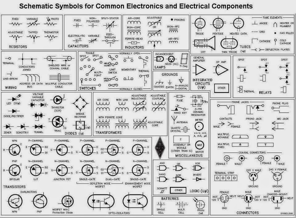
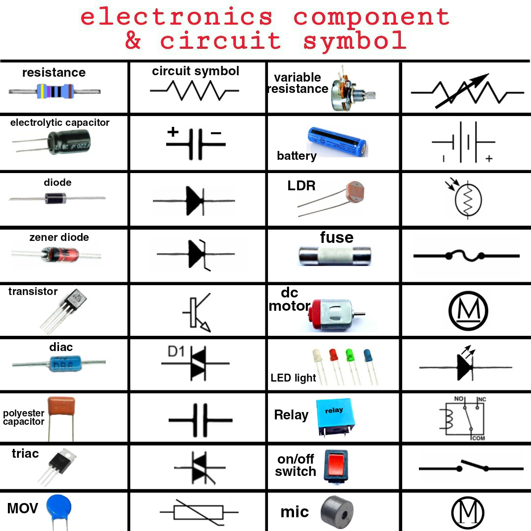
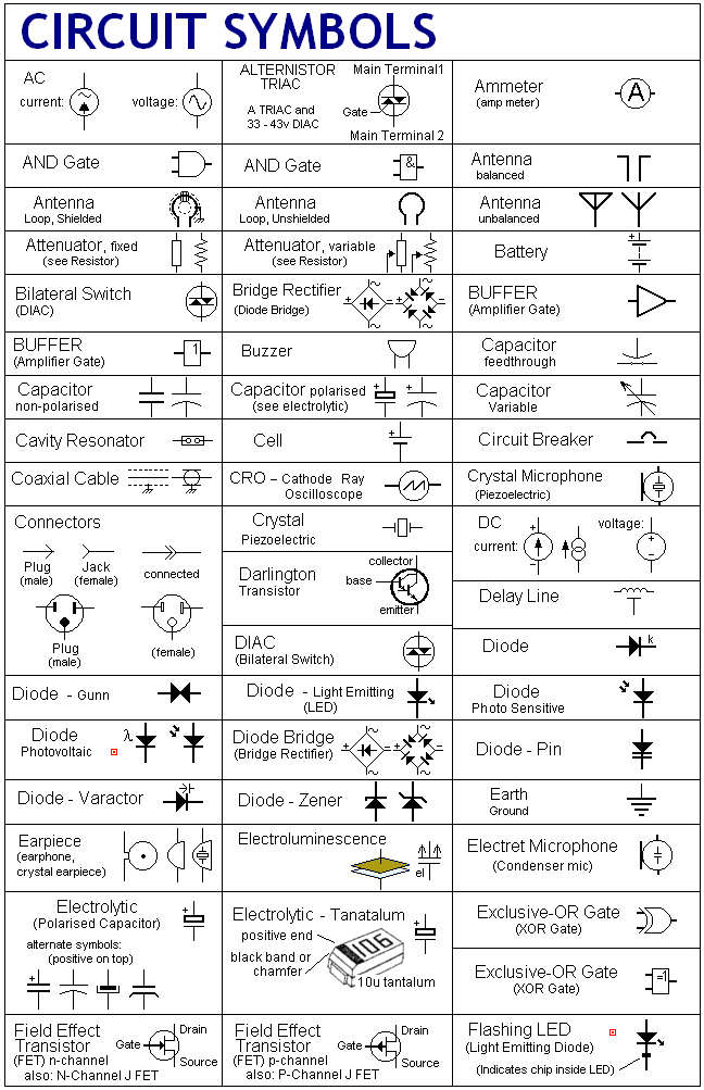
Ever wondered how those intricate circuit diagrams come to life? The key lies in understanding the language of electrical components symbols, often documented and shared via PDFs. These symbols are the building blocks of any electrical schematic, enabling engineers and hobbyists alike to communicate and construct complex circuits with clarity and precision.
Imagine trying to build a house without a blueprint. It would be chaotic, right? Similarly, in the world of electronics, electrical component symbols act as the blueprint, providing a visual representation of each component and how they interconnect. A downloadable PDF containing these symbols is an invaluable resource, allowing for easy sharing and access to standardized representations.
A standardized representation of electrical components is crucial for clear communication. Imagine the confusion if every engineer used different symbols for the same component. This is where standardized documentation, including electrical component symbol PDFs, becomes vital. They ensure everyone is speaking the same language, minimizing errors and misunderstandings.
Electrical component symbols have evolved over time, driven by the need for clarity and standardization across the growing field of electronics. Early diagrams were often crude and lacked consistency, leading to confusion and misinterpretations. The development of standardized symbols and their compilation into readily available PDFs has revolutionized circuit design and analysis.
Accessing these symbols in PDF format offers significant advantages. PDFs maintain formatting across different devices and operating systems, ensuring consistent viewing. They can be easily printed, shared, and archived, making them an ideal medium for distributing and preserving this vital information.
Historically, electrical diagrams were hand-drawn, a tedious and error-prone process. The advent of computer-aided design (CAD) software and the widespread use of PDFs marked a significant improvement. Now, creating, sharing, and modifying diagrams became significantly easier and more efficient.
A resistor, symbolized by a zigzag line, controls current flow. A capacitor, represented by two parallel lines, stores electrical energy. These symbols, and countless others, are the vocabulary of circuit design, and a comprehensive electrical component symbols PDF acts as the dictionary.
Utilizing a PDF of electrical components symbols offers several benefits. Firstly, it provides a readily available reference, eliminating the need to memorize countless symbols. Secondly, PDFs are easily searchable, allowing you to quickly locate specific components. Lastly, having a PDF ensures you are using the correct and up-to-date symbols, reducing the risk of errors in your designs.
Creating a simple circuit starts with sketching a schematic using the appropriate symbols from your PDF reference. Then, connect the components physically, ensuring they match the arrangement in your diagram. Finally, test the circuit to ensure it functions as intended.
Advantages and Disadvantages of Using Electrical Component Symbols PDF
| Advantages | Disadvantages |
|---|---|
| Easy to share and distribute | Can become outdated if not regularly updated |
| Portable and accessible on various devices | Requires a PDF reader |
| Preserves formatting consistency | Can be difficult to edit directly |
Best practices for using electrical component symbol PDFs include: ensuring the PDF is from a reputable source, verifying the version is up-to-date, using a clear and consistent naming convention for your files, organizing the PDF for easy navigation, and regularly reviewing and updating your symbol library.
Real-world examples of electrical component symbols in action include: designing a power supply circuit, creating a microcontroller-based project, analyzing an existing electronic device, troubleshooting a faulty circuit, and simulating circuit behavior using software.
Challenges in using electrical component symbols PDFs include keeping the library up-to-date and ensuring consistent usage across teams. Solutions include subscribing to updates from reputable sources and implementing standardized design practices within your organization.
Frequently asked questions include: "Where can I find a reliable PDF of electrical component symbols?", "How often are these symbols updated?", "What software can I use to create my own diagrams?", "Are there different standards for electrical symbols?", "How can I learn more about circuit design?", "What are the common mistakes when interpreting these symbols?", "How do I use these symbols in a simulation?", and "What resources are available for troubleshooting circuit issues?"
A helpful tip is to print out a laminated copy of your most frequently used symbols for quick and easy reference. Another trick is to create a digital folder on your computer dedicated to storing various versions of electrical component symbol PDFs.
In conclusion, understanding and utilizing electrical component symbols, often accessed through convenient PDF documents, is fundamental to anyone working with electronics. These symbols are the language of circuit design, enabling clear communication and accurate representation of complex systems. From designing new circuits to troubleshooting existing ones, a readily available reference of these symbols is invaluable. By embracing best practices and staying updated with the latest standards, you can effectively utilize electrical component symbol PDFs to enhance your understanding and proficiency in the world of electronics. So, explore the resources available, build your knowledge, and unlock the power of circuit design. Start your journey today by downloading a comprehensive PDF of electrical component symbols and embark on a fascinating exploration of the intricate world of electronics. Your future projects await!
Sparkle and shine exploring the world of lol dolls background images
Upgrade your footwear game jcpenney mens shoes online
Deciphering the language of safety emergency exit icons in floor plans


.jpg)


