Deciphering Electronics Symbols: A Guide to Circuit Language

The world of electronics, with its intricate circuits and complex components, often appears like a secret language to the uninitiated. But what if we could decipher this language, understanding the symbols that represent the building blocks of modern technology? This article explores the fascinating world of electronic symbols, providing a guide to their identification and meaning.
Imagine a beautifully tailored suit – each stitch, each button, meticulously placed to create a harmonious whole. Similarly, electronic circuits are crafted with precision, each component represented by a unique symbol, forming a visual language that dictates the flow of electricity. These symbols are the essential vocabulary of circuit design, allowing engineers to communicate complex ideas with clarity and efficiency. But which electronic symbol is shown? This depends on the specific context, as there are numerous symbols representing a vast array of components.
The identification of electronic symbols is crucial for anyone working with circuits, from seasoned engineers to aspiring hobbyists. Understanding these visual cues unlocks the secrets of circuit diagrams, allowing us to trace the path of current, predict circuit behavior, and troubleshoot malfunctions. This knowledge empowers us to build, repair, and innovate in the realm of electronics.
The history of electronic symbols is intertwined with the development of electronics itself. As circuits became more complex, the need for a standardized system of representation became apparent. Over time, a universal language of symbols emerged, evolving alongside the technology it represented. This evolution has led to the sophisticated symbols we use today, each carefully designed to convey specific information about the component it represents. For instance, recognizing a diode symbol tells us about its unidirectional current flow, while a transistor symbol indicates its amplifying capabilities.
The importance of accurately representing electronic components cannot be overstated. A misidentified symbol can lead to faulty circuit designs, malfunctioning devices, and even safety hazards. Therefore, a thorough understanding of electronic symbology is paramount for anyone working with electronics. Understanding "what electronics symbol is shown" becomes a critical question in any circuit analysis.
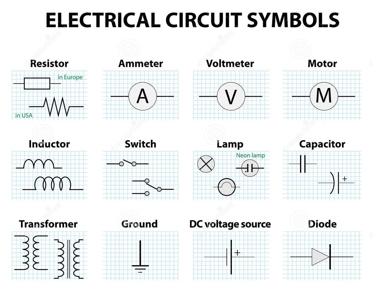
Electronic symbols are graphical representations of electronic components used in circuit diagrams. A simple example is the resistor symbol, which is a zigzag line. This symbol signifies resistance to the flow of current. Another common example is the capacitor symbol, represented by two parallel lines. This denotes its ability to store electrical charge.
One benefit of using standardized electronic symbols is clarity. They provide a universal language understood by engineers worldwide, facilitating collaboration and knowledge sharing. For example, a circuit diagram using standard symbols can be interpreted by engineers in different countries without language barriers. Secondly, efficiency is greatly enhanced. Symbols allow for compact representation of complex circuits, making diagrams easier to read and understand. Finally, accuracy is paramount. Standard symbols eliminate ambiguity, ensuring that the intended circuit design is clearly conveyed. This helps prevent errors during circuit construction and testing.
Advantages and Disadvantages of Standardized Electronic Symbols
| Advantages | Disadvantages |
|---|---|
| Clarity and Universal Understanding | Requires Learning and Memorization |
| Efficiency in Circuit Representation | Can be Complex for Beginners |
| Accuracy and Reduced Ambiguity | Variations Exist Across Different Standards |
Frequently Asked Questions:
1. What does the resistor symbol look like? A zigzag line.
2. What does the capacitor symbol represent? The ability to store electrical charge.
3. Why are electronic symbols important? For clear and accurate circuit design.
4. How can I learn electronic symbols? Through online resources, textbooks, and practical experience.
5. What are some common electronic symbols? Resistor, capacitor, diode, transistor, inductor.
6. What happens if an electronic symbol is misidentified? It can lead to faulty circuit designs and malfunctions.
7. Where can I find a comprehensive list of electronic symbols? In electronics textbooks and online resources.
8. How do electronic symbols contribute to circuit analysis? They provide a visual representation of the circuit's components and their connections, aiding in understanding the circuit's functionality.
Tips and tricks for learning electronic symbols include using flashcards, practicing drawing circuits, and using online simulators. Building simple circuits and identifying the components in real-world electronics can also enhance understanding.
In conclusion, the seemingly complex world of electronics is built upon a foundation of symbols, a visual language that unlocks the secrets of circuit design. Understanding "what electronics symbol is shown" is fundamental to navigating this landscape. From the simple resistor to the complex integrated circuit, each symbol carries a wealth of information, guiding the flow of electrons and shaping the technology that powers our modern world. By learning this language, we empower ourselves to understand, create, and innovate in the exciting field of electronics. Mastering electronic symbols is not just about memorization; it's about developing a deeper understanding of how circuits function and how to communicate electronic designs effectively. This knowledge opens doors to a world of possibilities, enabling us to build, repair, and design electronic systems that shape our everyday lives. Embrace the challenge, explore the resources available, and unlock the potential within this intricate and fascinating field.
Decoding that annoying itchy rash from the sun
Unlocking smooth towing your guide to trailer bearing torque specifications
Aarp supplemental insurance decoding the coverage maze


